Tolerances and Manufacturing Capabilities
Useful information about manufacturing tolerances offered at LaserBoost, certified by our staff and in correlation with our production facility.
Content
Tolerances – Material
-
Thickness >Thickness >
Tolerances and Laser Cutting Capacities
-
Cutting Tolerances >Cutting Tolerances >
Tolerances and Bending Capabilities
-
Contents >Contents >
-
Other Considerations about Bendings >Other Considerations about Bendings >
Tolerances and Countersink Capabilities
-
Countersink Tolerances >Countersink Tolerances >
Click on the topics to access them.
Tolerances – Material
> Material – Thickness
At LaserBoost, we use top-quality materials from leading manufacturers in Northern Europe. Our material suppliers comply with ISO and EN standards for the supply of flat metal materials. The following table shows the specific standard that applies to each material.
Material
The applicable standard
Carbon steel
Galvanized steel
IN 10346
Aluminum
IN 485
Stainless Steel
ISO 9444 / ISO 9445
Brass
IN 12165
Copper
IN 12165
The material thickness can be affected by the finishes we offer. Below, we show the estimated value of thickness loss according to each finish:
Finish
Effect
Thickness loss (mm)
Natural or undetermined
Inappreciable
Not applicable
Sanding
Low
-0.10
Tumbling
Average
-0.10
Premium Brushed
High
-0.10
Premium Bright
High
-0.10
The thickness loss values for finishes with a “High” effect on the material can be up to 30% higher than those shown for soft materials such as Aluminum, Copper, or Brass.
Tolerances and Laser Cutting Capacities
> Laser Cutting – Cutting Tolerances
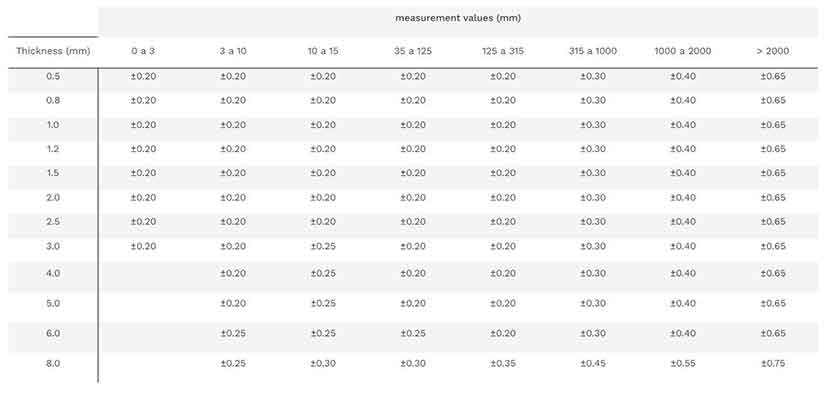
At LaserBoost, we use nitrogen cutting, which enables us to perform very precise and clean cuts. Below, we show the cutting tolerances based on material thickness and measurement values.
Measurement values (mm)
Thickness (mm)
0 to 3
3 to 10
10 to 15
15 to 35
35 to 125
125 to 315
315 to 1000
1000 to 2000
> 2000
0.5
±0.20
±0.20
±0.20
±0.20
±0.20
±0.20
±0.30
±0.40
±0.65
0.8
±0.20
±0.20
±0.20
±0.20
±0.20
±0.20
±0.30
±0.40
±0.65
1.0
±0.20
±0.20
±0.20
±0.20
±0.20
±0.20
±0.30
±0.40
±0.65
1.2
±0.20
±0.20
±0.20
±0.20
±0.20
±0.20
±0.30
±0.40
±0.65
1.5
±0.20
±0.20
±0.20
±0.20
±0.20
±0.20
±0.30
±0.40
±0.65
2.0
±0.20
±0.20
±0.20
±0.20
±0.20
±0.20
±0.30
±0.40
±0.65
2.5
±0.20
±0.20
±0.20
±0.20
±0.20
±0.20
±0.30
±0.40
±0.65
3.0
±0.20
±0.20
±0.25
±0.25
±0.20
±0.20
±0.30
±0.40
±0.65
4.0
±0.20
±0.25
±0.25
±0.20
±0.20
±0.30
±0.40
±0.65
5.0
±0.20
±0.25
±0.25
±0.20
±0.20
±0.30
±0.40
±0.65
6.0
±0.25
±0.25
±0.25
±0.25
±0.20
±0.30
±0.40
±0.65
8.0
±0.25
±0.30
±0.30
±0.30
±0.35
±0.45
±0.55
±0.75
Example, part with thickness 1mm >
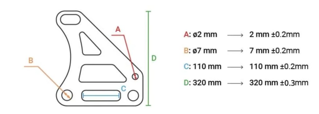
The shown tolerances will be met as long as the guidelines for flat laser cutting and the guidelines for laser cutting with bending are followed.
> Laser Cutting – Minimum perforations
For a proper cut, we require that all perforations have a minimum diameter.
Thickness t (mm)
Minimum Diameter d (mm)
0.5
0.5
0.8
0.5
1.0
0.5
1.2
0.8
1.5
0.8
2.0
1.5
2.5
2.0
3.0
2.5
4.0
2.5
5.0
3.5
6.0
4.0
8.0
5.0
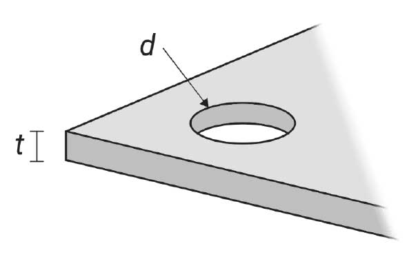
In aluminum, the value of Esperor (t) is equal to the value of the minimum diameter (d).
> Laser Cutting – Minimum Bridges and Distance to the Nearest Vertices
To avoid burns or irregularities in the narrow areas of the part, we need them to meet a minimum distance. This also applies to the minimum distance between the cutouts and the outer edge of the part.
Thickness t (mm)
Minimum Space s (mm)
0.5
0.5
0.8
0.5
1.0
1.0
1.2
1.0
1.5
1.5
2.0
1.5
2.5
1.75
3.0
2.1
4.0
2.8
5.0
3.5
6.0
4.2
8.0
5.6
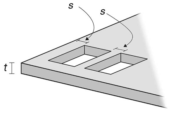
In aluminum, the value of Esperor (t) is equal to the value of the minimum diameter (d).
> Other considerations about laser cutting
Heat-induced deformations
Our cutting process subjects the part to high temperatures. A very high cutting density can generate deformations or oscillations in the part. For example, a large-sized grid. More information is available in our design guide for flat laser cutting.
Part flatness
The materials used in LaserBoost comply with European flat rolled supply regulations, including their flatness. However, this may not be directly related to the final flatness of the part, which depends on its length and can be affected by its design or even gravity. For example, a 1mm thick part measuring 2000mm x 5mm may experience a lack of flatness.
Tolerances and Bending Capabilities
> Bending Tolerances
At LaserBoost, we work with the technique of air bending, using punch and die. Below, we show the bending tolerances with some basic shapes as examples. For more complex parts, you need to add the values for each shape present. The tolerance values vary according to the material thickness.
Thickness (mm)
E
F (grade)
0.5mm ~ 3mm
±0.20
±0.60
±1.00
±0.60
±0.6º
±0.5º/100mm
4mm
±0.40
±0.70
±1.40
±0.70
±0.6º
±0.5º/100mm
5mm – 6mm
±0.50
±1.00
±1.90
±1.00
±0.6º
±0.5º/100mm
8mm
±0.60
±1.2
±2.40
±1.20
±0.6º
±0.5º/100mm

> Bending Radious
At LaserBoost, we require that the exterior radius of the parts be designed with a value two times equal to the thickness of the material (this value is mechanically most optimal). We use the necessary bending tools to reproduce these radii within specific tolerances based on the material thickness. This value is maintained regardless of the angle, from 0º to 180º.
Thickness t (mm)
CAD Interior Radius
CAD Exterior Radius
Real External Radio (mm)
0.5
0.5
1.0
1.50± 0.25
0.8
0.8
1.6
2.00± 0.25
1.0
1.0
2.0
2.25± 0.25
1.2
1.2
2.4
2.50± 0.25
1.5
1.5
3.0
3.00± 0.25
2.0
2.0
4.0
4.00± 0.25
2.5
2.5
5.0
3.00± 0.25
3.0
3.0
6.0
6.50± 0.25
4.0
4.0
8.0
9.00± 0.25
5.0
5.0
10.0
11.50± 0.25
6.0
6.0
12.0
12.00± 0.25
8.0
8.0
16.0
14.00± 0.25
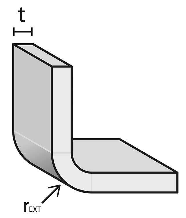
Currently, we cannot perform bendings with different radious from those shown.
Tolerances and Countersink Capabilities
> Countersink Tolerances
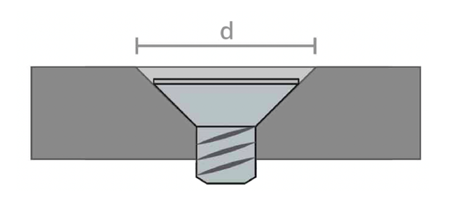
We use industrial tools for countersinking to ensure precision in the manufacturing process. The method varies depending on the size of the part:
- For dimensions under 1000 mm, we use a pneumatic countersinking tool, which provides high accuracy with a tolerance of ±0.2 mm (d).
- For dimensions over 1000 mm, we use a manual drill, which allows us to work with larger parts but results in a slightly higher tolerance of ±0.5 mm (d).
These processes ensure functional countersinks while maintaining quality standards.
Any questions? The technical team at LaserBoost is at your disposal to assist with your design and validate its manufacturing feasibility.
Contact us here.
Regarding the User Guides, Tolerances, and Production Capacities of LaserBoost’s service, it is possible to manufacture parts correctly that do not meet the capacities advertised here. However, LaserBoost does not guarantee the correct result of cutting and/or bending if the specifications mentioned on our website are not met. If a design does not meet any of the tolerances, capacities, or limitations announced, it can be produced by LaserBoost at the customer’s risk. You can validate the proper producibility of your design prior to placing the order by contacting our technical team at info@laserboost.com.
For more information about using our platform, you can visit our Terms & Conditions of Service.
